Monitoring Pylontech Batteries with Raspberry Pi 4 and ICM-PI Solar Software
Explore Emil's project on monitoring solar system batteries using a Raspberry Pi 4, ICM-PI Solar Software, and a custom USB to RS232 cable.
Monitoring a solar system in real time can be tricky, especially when working with different components. Recently, I set up a custom monitoring system for a solar battery setup, which includes:
- 🔋 4 Pylontech batteries
- ⚡ Steca Solarix PLI 48-5000 inverter
- 🖥️ Raspberry Pi 4 (4GB RAM) running ICM-PI Solar software
The challenge? Getting my Raspberry Pi to communicate directly with the Pylontech batteries via the RJ11 port. Most solutions rely on reading batteries values from inverter, but this is not precise at all.
The Solution: A Custom USB to RJ11 (RS232 Serial) Cable
Instead of using a pre-made adapter, I built a custom USB to RJ11 cable to connect the Pylontech battery directly to the Raspberry Pi. This allowed me to:
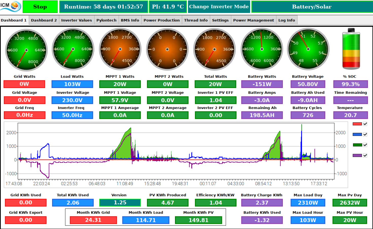
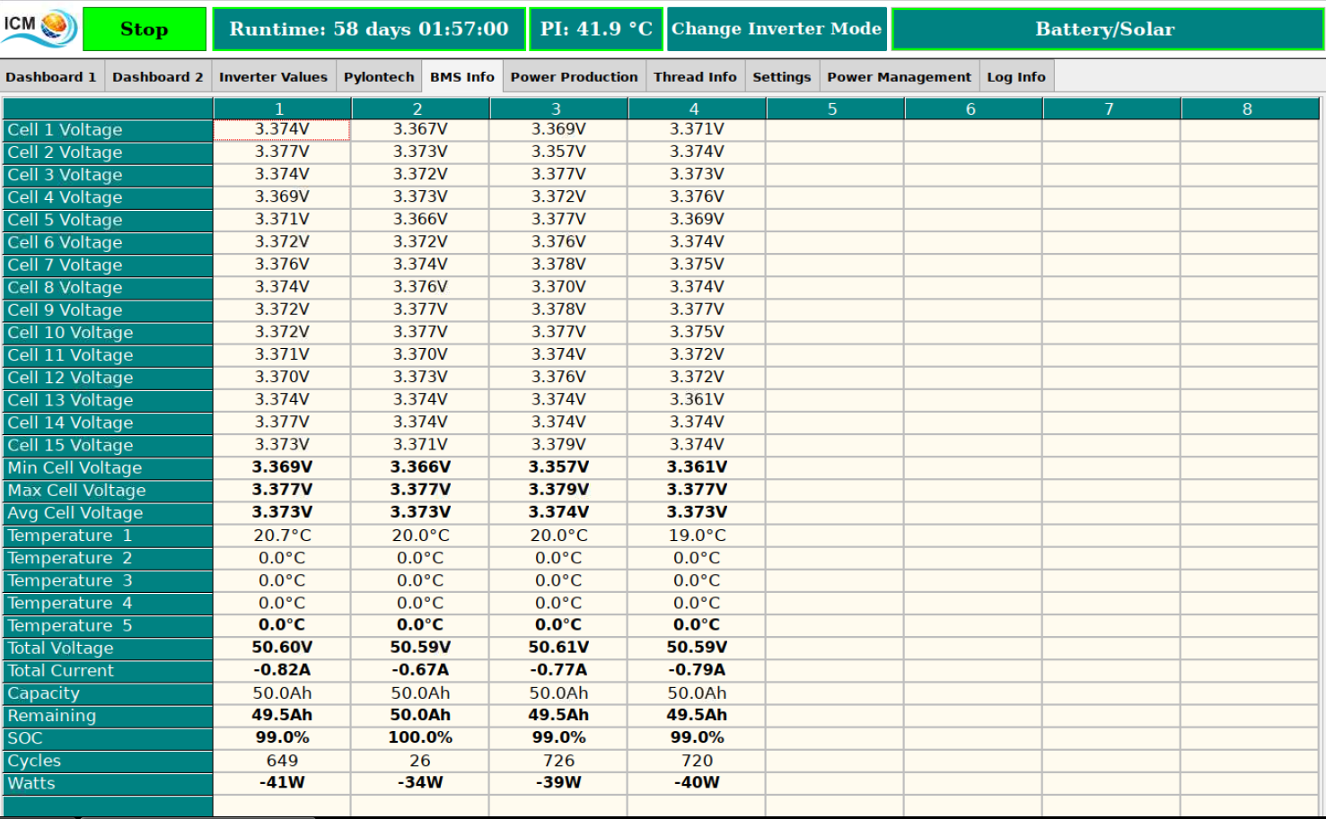
✅ Read real-time battery voltage, SOC (State of Charge), and current flow
✅ Optimize charge and discharge cycles for better efficiency
✅ Feed data into ICM-PI Solar for real-time monitoring and automation
Key Challenges & How I Solved Them
1. Understanding the Pylontech RS232 Communication
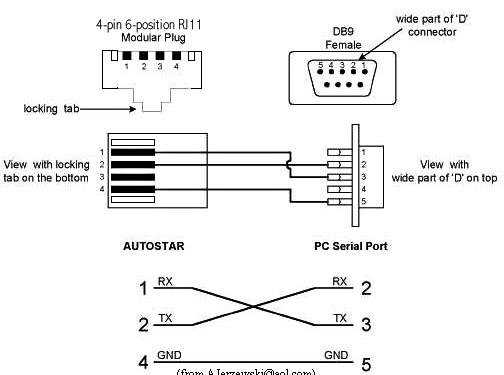
Pylontech batteries use RS232 for communication, via a RJ11 connector. The key pins for serial communication are:
| Pin | Function | Connection |
|---|---|---|
| 2 | TX (Transmit) | Connect to RX on Raspberry Pi |
| 3 | RX (Receive) | Connect to TX on Raspberry Pi |
| 5 | GND (Ground) | Connect to GND on Raspberry Pi |
Since RS232 operates at different voltage levels (±12V) than the Raspberry Pi’s UART (3.3V TTL), a RS232-to-USB adapter or RS232-to-TTL converter is required.
2. Building the Custom RS232 Cable
To interface with my Raspberry Pi, I used:
- An RS232-to-USB adapter with an FTDI (compatible with Linux)
- A DB9 female connector
- A RJ11 connector
- A RJ11 crimp tool
- Correct wiring between DB9 to RJ11
3. Configuring ICM-PI Solar on Raspberry Pi
Once the cable was connected, I followed these steps:
- Connected the RS232 adapter to the Raspberry Pi via USB.
- Checked the device name with:
1
lsusb
1
ls /dev/ttyUSB*
- Set correct permissions (if needed):
1
sudo chmod 777 /dev/ttyUSB0 - Configured ICM-PI Solar to read battery data from /dev/ttyUSB0 with the correct baud rate (in this case 115200).
4. Create a new udev rule
For a stable system we need to create a new udev rule to have a unique device name after reboot.
Create file 99-usbserial.rules in /etc/udev/rules.d:
1
touch /etc/udev/rules.d/99-usbserial.rules
Add the following rule to the created file (you need to replace your-device-vendor and your-device-id-product with your own device vendor and product id using lsusb command):
1
echo 'SUBSYSTEM=="tty", ATTRS{idVendor}=="your-device-vendor", ATTRS{idProduct}=="your-device-id-product", SYMLINK+="ttyUSBPylontech"' > /etc/udev/rules.d/99-usbserial.rules
The Result?
A real-time battery monitoring system that provides detailed insights into the solar setup-without relying on expensive adapters or third-party solutions!
If you’re working on a similar project or need help setting up your solar battery monitoring 🔌🔋, feel free to reach out!


